KEY FACTORS FOR IMAGING SUCCESS
To achieve consistent, accurate results in total hip replacement, it's essential to understand what you are seeing in fluoroscopic images and the factors that influence the images you see. Your perception of these images is affected by factors including distortion, parallax, and changes in a patient's pelvic tilt or leg position during surgery.
Let's take a look at them and explore how to set yourself up for success, one reproducible hip at a time:
PARALLAX
Note that all C-arm images are subject to parallax effect
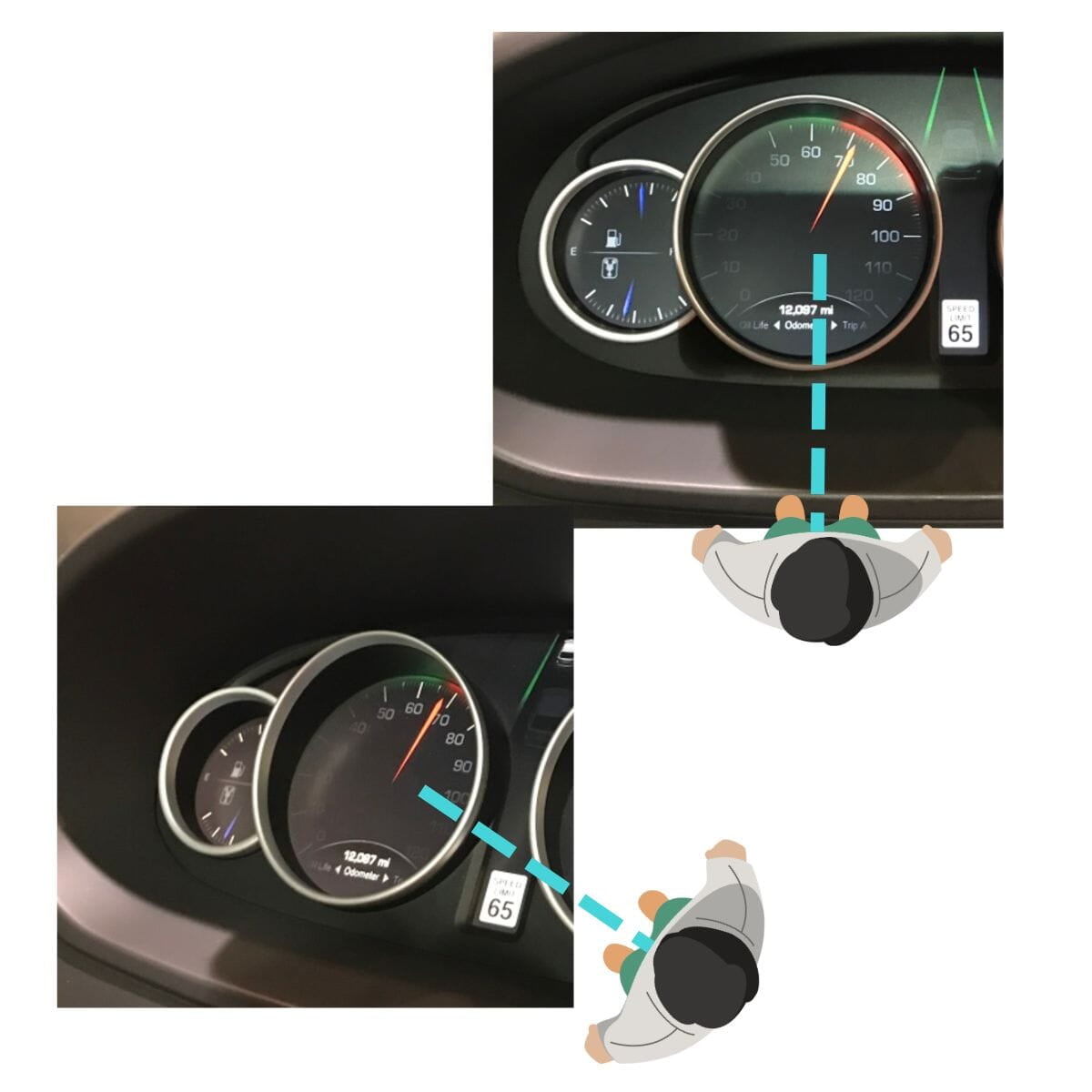
- Parallax is the difference in the perceived position of an object when viewed from line-of-sight angles that are not directly in front of it.
- In fluoroscopy, parallax can lead to different apparent relationships between landmarks which can affect measurement.
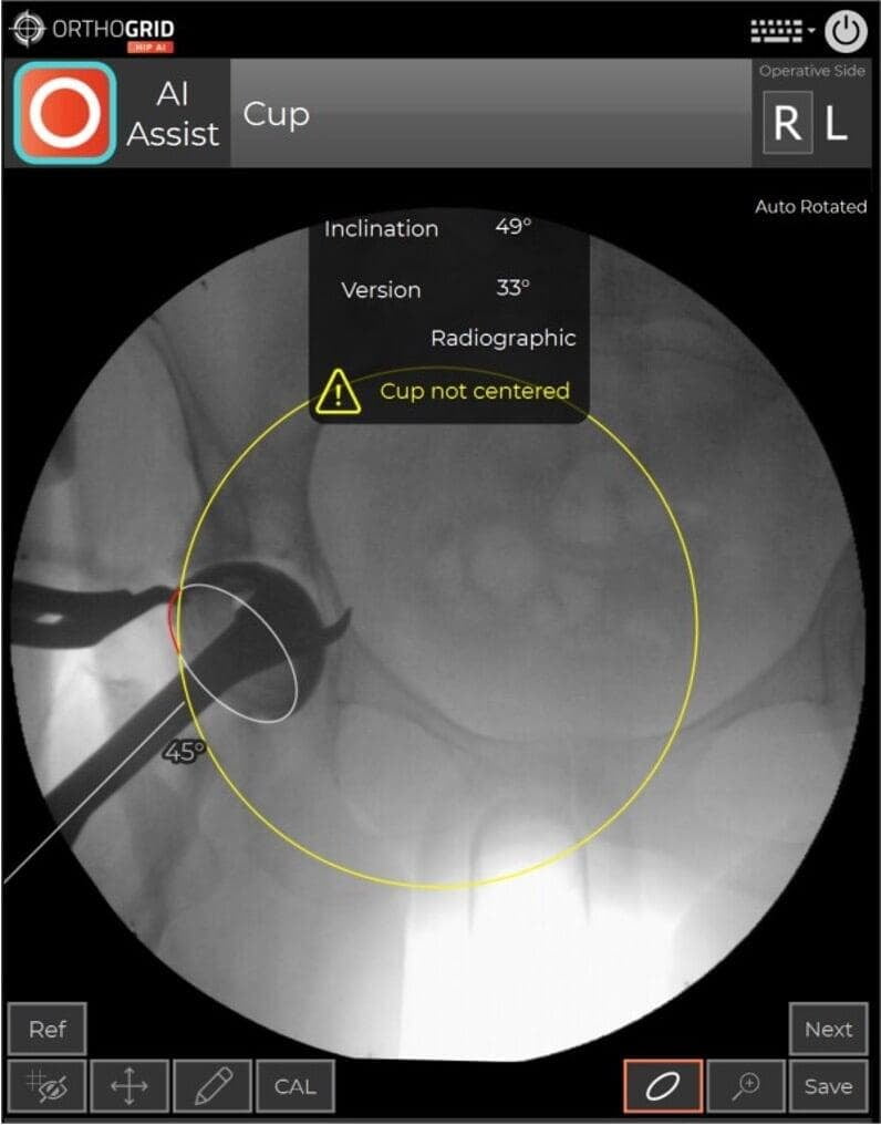
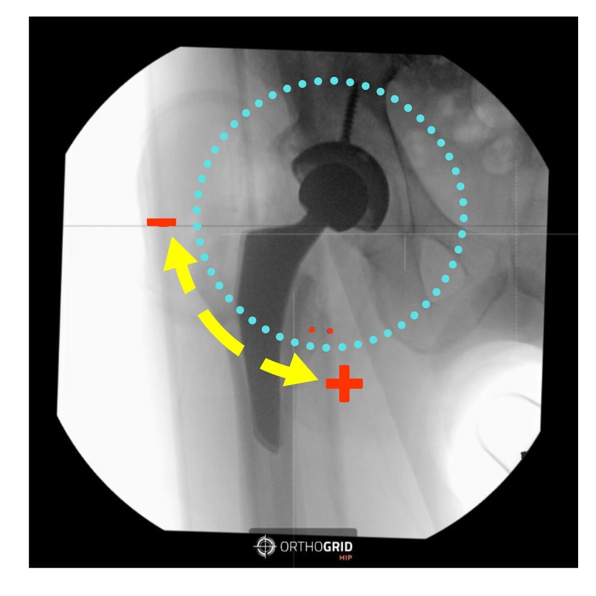
- If your cup is not in the center of the image, the cup measurement can be influenced by parallax. You'll see the Hip AI warning message. Retake image and center the Cup while keeping both Teardrops in view to Keep the Pelvis Tracking
DISTORTION IN IMAGE INTENSIFIERS
Note that all Image Intensifiers have distortion. Images taken with flat panel C-arms do not have distortion.
PINCUSHION DISTORTION
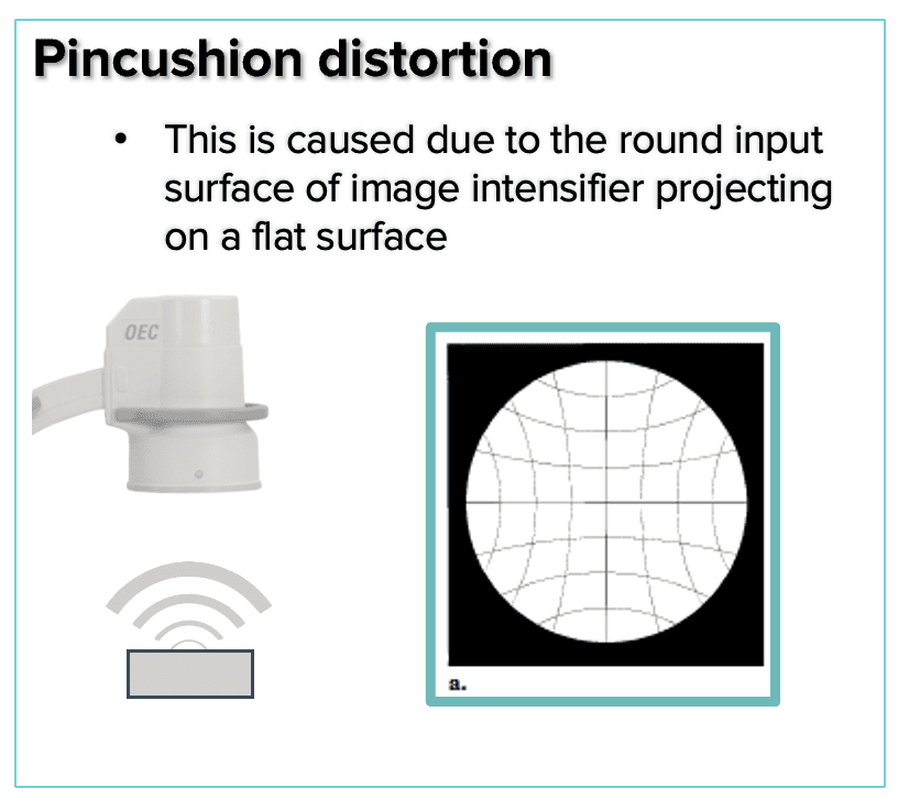
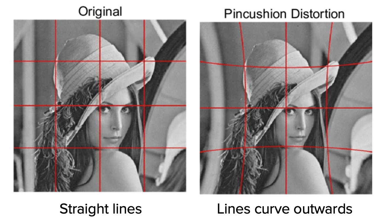
- Pincushion distortion is a geometric, nonlinear magnification across the image
- The magnification difference at the periphery of the image results from the projection of the x-ray beam onto a curved input surface
- The distortion can be visualized by using a fluoroscope to capture an image of a rectangular grid as shown
S- DISTORTION
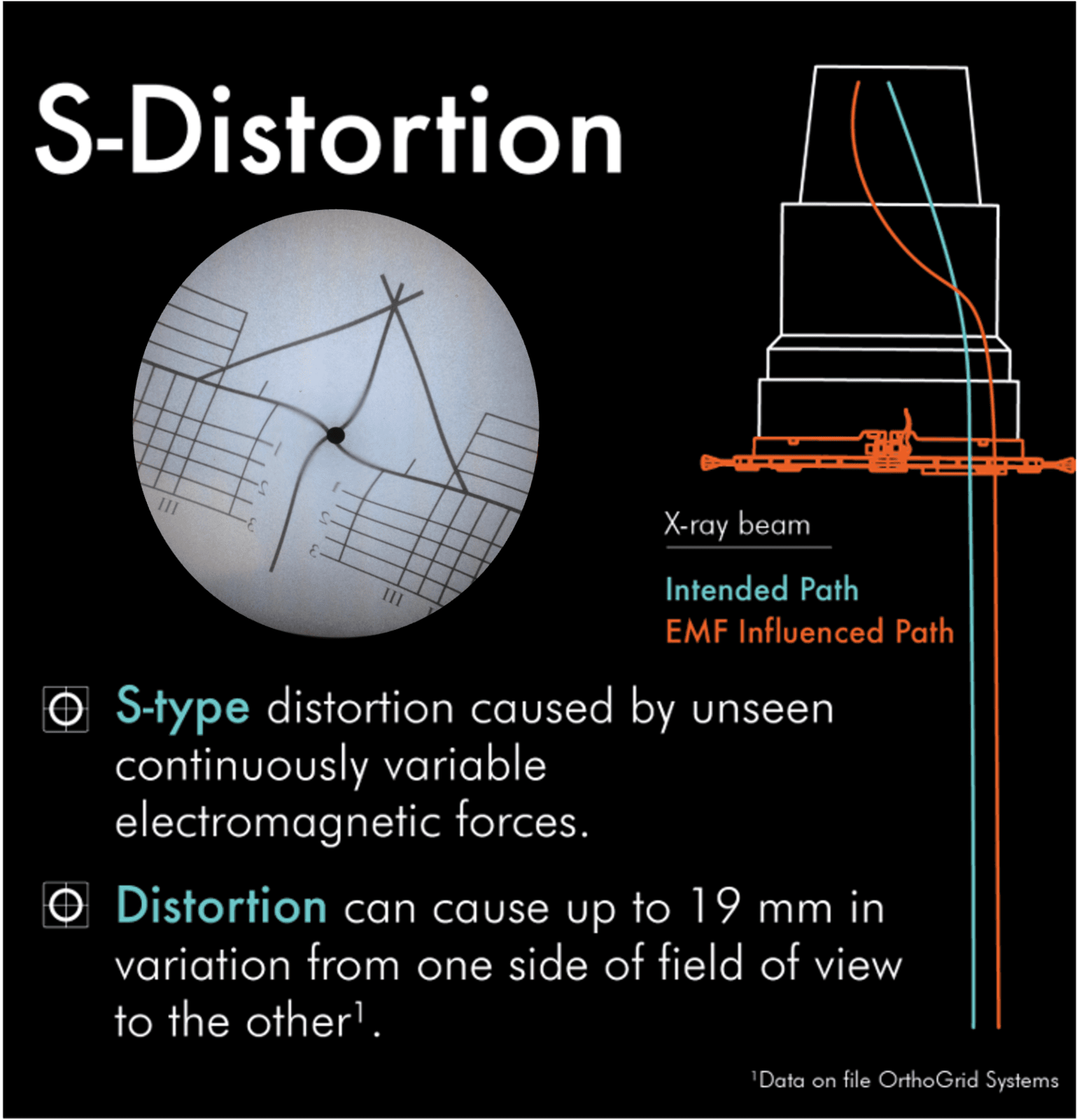
- Electrons within the image intensifier move in paths along designated lines of flux.
- External electromagnetic sources affect these electron paths at the perimeter of the image intensifier more than those nearer the center.
- This causes the image in a fluoroscopic system to distort with an s-shape.
- Larger image intensifiers are more sensitive to the electromagnetic fields that cause this distortion
ACHIEVING A FUNCTIONAL PELVIS
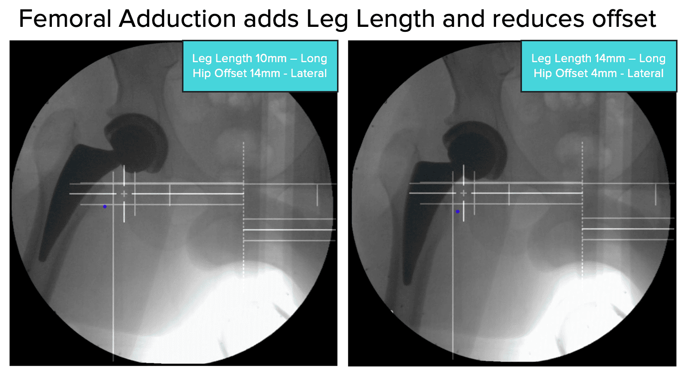
CHECK LEG POSITIONING FOR ACCURATE LEG LENGTH AND OFFSET MEASUREMENTS
- Check Leg Abduction/Adduction - the live image should replicate the reference image. Femoral Abduction adds leg length but reduces offset.
- Make sure that the rotation of both femurs is the same - check that the Lesser Trochanters are equal on each side.
BEST PRACTICES FOR C-ARM USE
1) Pre-op C-arm Set up
- Set to ORTHO
- Set to AUTO CONTRAST – you want to be able to identify key anatomic points.
- Position the C-arm perpendicular to the patient.
- Set the boom in the middle position (10) to allow for translation
2) Establish your Reference Image
- The first image will be the patient's pelvis. Take care to create mirror symmetry of the hemi-pelvises. (Optional: recreate the patient’s functional pelvis using the pre-operative standing films as a reference.)
- Check pelvic tilt by comparing inlet/ outlet views/
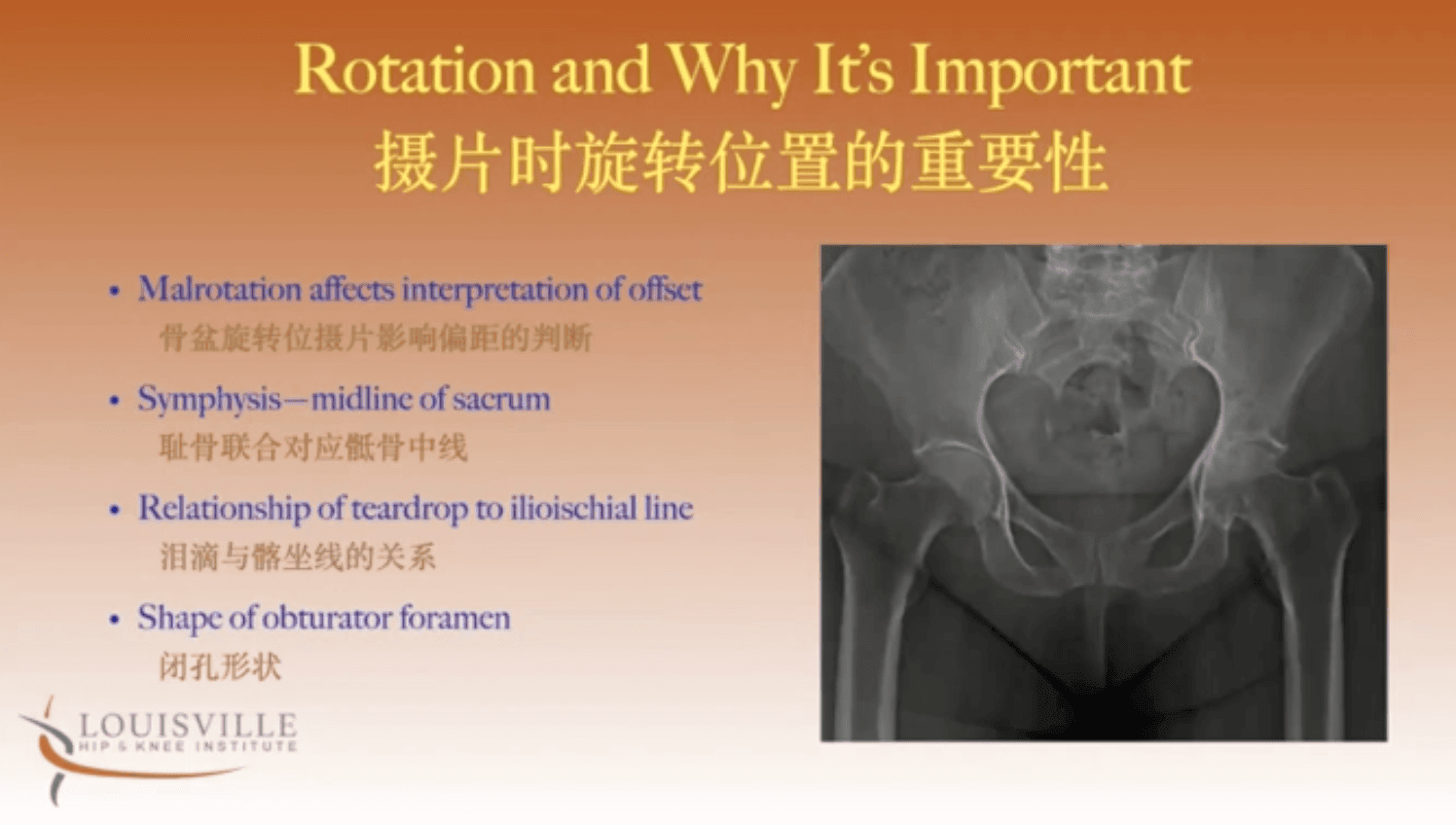
- Check for rotation – Check that the sacrum and symphysis pubis line up, compare the symmetry of foramen and check the relationship between teardrops and iliioischial line - are they equidistant on both sides?
- Set the reference image. (SAVE REF button)
- Once you have the reference images, HipAI can offer guidance on how to maintain or re-create your reference images throughout the remainder of the procedure.
3) Mark your C-arm position
- Before moving the C-arm – mark its position on the ground – we like to use tape or dry erase markers to mark around the corners. This makes it easy to exactly re-position the C-arm after it has moved. Lock the base to avoid the supermarket wheel effect – you want to move only forward and back).
4) Hana Table Considerations
- Use the Shortest Perennial post possible so that the C-arm can be lowered thereby maximizing field of view.
- Consider your neutral position with the handles touching to control for abduction.
- Avoid moving the non-operative limb so that the neutral position remains constant.
- Trust the image symmetry.
INTRAOP IMAGING CHECKLISTS
- A step by step guide of the iamges to take during each workflow in both AP Pelvis and AP Hip Workflows
@2024. All rights reserved. OrthoGrid Systems.